-40%
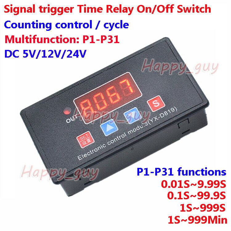
USA! 2 PCS12 VDC PLC CYCLE TIMER MULTIFUNCTION DELAY MODULE NEGATIVE TRIGGER !!
$ 13.46
- Description
- Size Guide
Description
2 PC OF A 12VDC PLC MULTIFUNCTION PROGRAMMABLE 10 AMP RELAY BOARD WITH A NEGATIVE TRIGGERA VERY IMPRESSIVE PRODUCT , STILL A LOT OF GOOD FUNCTIONS , WITH AND WITHOUT , LOW SIGNAL NEEDED . HAS SOME FUNCTIONS THAT ARE CYCLE RELAY ON FOR ADJUSTABLE TIME , THEN OFF FOR ADJUSTABLE TIME , THEN REPEATS , OR CAN SET TO RECEIVE ANOTHER LOW PULSE BEFORE REPEATING SET TIMES , NICE !!
PLEASE ASK IF WHAT YOU WOULD NEED IT TO DO , IS POSSIBLE . I WILL SET ONE UP FOR YOUR RECOMMENDATION TO ENSURE THE FEATURE WILL WORK !! , SHIPS OUT SAME DAY OR WITHIN 24 HOURS OF CLEARED PAYMENT NEXT WORKING DAY , USPS MAIL
Tips: Functional 1-8 on power-up self-start function , 9-18 require high LOW signal (LOW-level duration of not less than 20ms, hereinafter the same) trigger the start.
Function 1:
Timing Pick: After power, time delay relay pull T1, T1 between 1 second -270 hours adjustable, CH1 interface to a low level pulse signal, repeat the above functions;
Function 2:
Timing off: when the power relay, time delay relay disconnected T1, T1 between 1 second -270 hours adjustable, CH1 interface to a low level pulse signal, repeat the above functions;
Function 3:
Timing pull off again: After power relay to not pull, the delay time T1 reaches the relay is energized; pull the relay off after T2 arrival time, delay time T1 and T2 in 1 second -270 hours between adjustable, CH1 interface to a
low pulse signal, repeat the above functions;
Function 4:
Timing and then pull off: After power, immediately pull the relay, the relay off delay time T1 after arrival; T2 arrive after disconnecting time relay, -270 hour in 1 second delay time between T1 and T2 adjustable to CH1 interface a low pulse signal, repeat the above functions;
Function 5:
Infinite loop timing mode 1: After power relay to not pull, after the delay time T1 reaches the relay is energized; pull the relay off after time T2 arrives, and then repeat the above condition, the delay time T1 and T2 at 1 adjustable between 1 second -270 hours, giving a low level pulse signal CH1 interface, you can restart the above functions;
Function 6:
Infinite loop timing mode 2: After power, immediately pull the relay delay time T1 reaches the relay off; arrive after disconnecting time T2 relay, and then repeat the above condition, the delay time T1 and T2 in 1 second adjustable between -270 hours, giving a low level pulse signal CH1 interface, you can restart the above functions;
Function 7:
Finite loop timing mode 1: 5 on the basis of functionality, increasing the number of cycles function, this time between T1 and T2 in 1 second -9999 seconds adjustable cycles NX adjustable between 1-9999 times to CH1 interface a low pulse signal, the above functions can be re-started;
Function 8:
Finite loop timing mode 2: 6, on the basis of the function, increasing the number of cycles function, this time between T1 and T2 in 1 second -9999 seconds adjustable cycles NX adjustable between 1-9999 times to CH1 interface a low pulse signal, the above functions can be re-started;
Function 9:
Latching relay modes: CH1 interface to relay a low level pulse signal, relay, give a low pulse signal relay disconnected.
Function 10:
Trigger relay modes: CH1 interface to a low signal relay, relay, low disappear, relay disconnected.
Function 11:
Pull the trigger timing: After power relay does not act, a low-level interface to CH1 pulse signal, the delay time relay pull T1, T1 between 1 second -270 hours adjustable, repeating a low level interface to CH1 pulse signal, repeat the above function;
Function 12:
Trigger timing off: After power relay does not act, a low-level interface to CH1 pulse signal relay, the relay off delay time T1, T1 between 1 second -270 hours adjustable, repeat to CH1 interface a low pulse signal, repeat the above functions;
Function 13:
Pull the trigger timing then disconnect: After power relay does not act, CH1 interface to a low level pulse signal, the delay time T1 reaches the relay is energized; pull the relay off after T2 arrival time, delay time T1 and T2 between 1 second -270 hours adjustable, repeat CH1 interface to a low level pulse signal, repeat the above functions;
Function 14:
Disconnect and then pull the trigger timing: After power relay does not act, a low-level interface to CH1 pulse signal, immediately pull the relay, the relay off delay time T1 after arrival; T2 arrive after disconnecting time relay, delay time between T1 and T2 in 1 second -270 hours adjustable, repeat CH1 interface to a low level pulse signal, repeat the above functions;
Function 15:
Infinite loop timing mode 1: After power relay does not operate to a low level pulse signal CH1 interface, the delay time T1 reaches the relay is energized; pull off the relay arrival time T2, and then repeat the above condition, the extension when the time between T1 and T2 in 1 second -270 hours adjustable, repeat CH1 interface to a low level pulse signal, the above functions can be re-started;
Function 16:
Infinite loop timing mode 2: After power relay does not act, a low-level interface to CH1 pulse signal, immediately pull the relay, the relay off delay time T1 after arrival; break time T2 after reaching relay, then repeat the above condition, the delay time between T1 and T2 in 1 second -270 hours adjustable, repeat CH1 interface to a low level pulse signal, the above functions can be re-started;
Function 17:
Finite loop timing mode 1: 15 on the basis of functionality, increasing the number of cycles function, this time between T1 and T2 in 1 seconds -9999 seconds adjustable cycles NX adjustable between 1-9999 times, repeating to CH1 interface a low pulse signal, the above functions can be re-started;
Function 18:
Finite loop timing mode 2: 16 on the basis of functionality, increasing the number of cycles function, this time between T1 and T2 in 1 seconds -9999 seconds adjustable cycles NX adjustable between 1-9999 times, repeating to CH1 interface a low pulse signal, the above functions can be re-started;
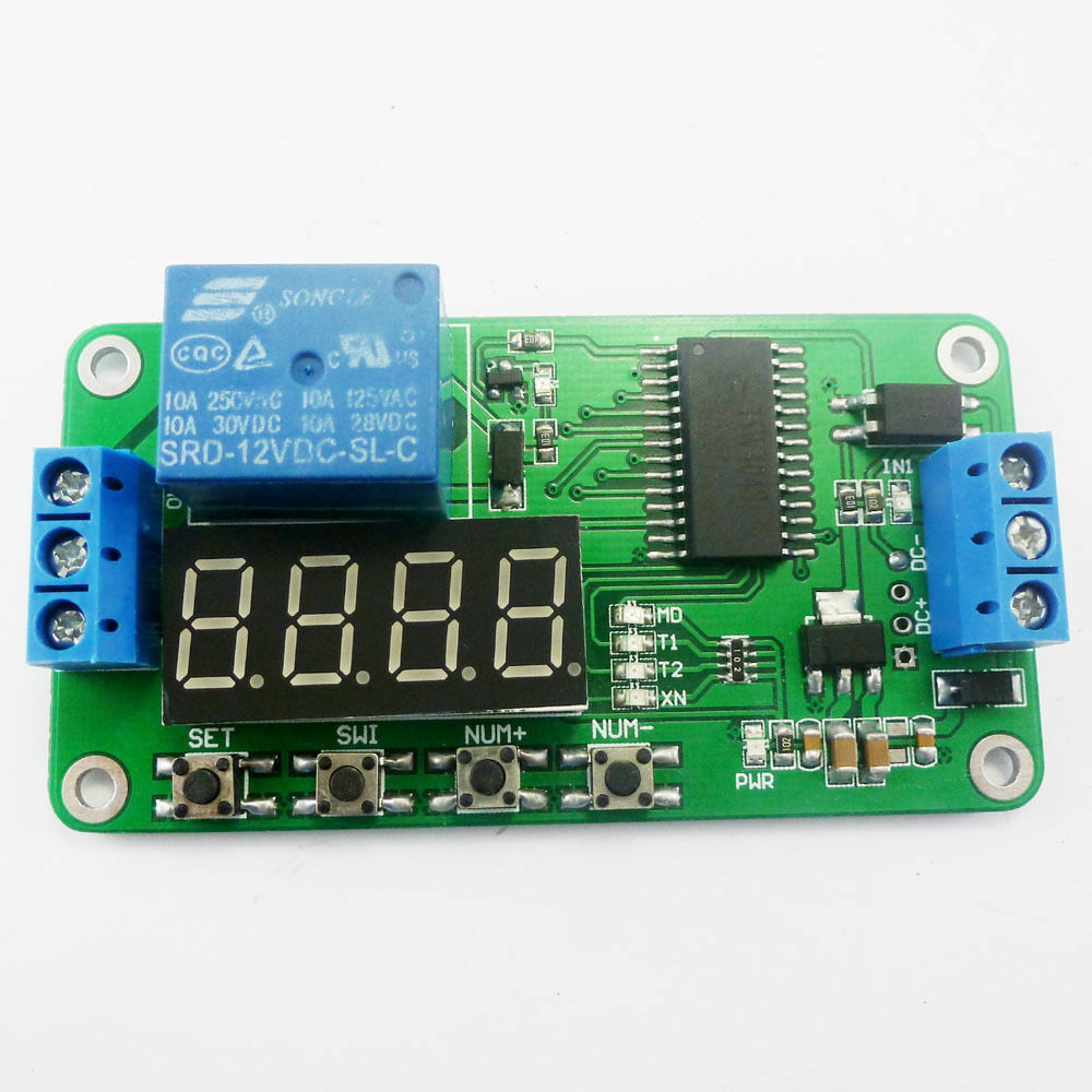
SETTING INSTRUCTIONS ; THESE ARE VERY MUCH LIKE SETTING AN OLD DIGITAL WATCH , JUST PRESS THE SET BUTTON UNTIL THE DISPLAY FLASHES , IT STARTS WITH THE LED BLINKING BESIDE THE "MD"= MODE , USE THE NUM- & NUM+ BUTTONS TO ADJUST IT UP OR DOWN , ALSO THE "SWI" BUTTON WILL CHANGE THE DISPLAY SETTING TO THE NEXT DIGIT , AFTER SETTING THE MODE , PRESS THE SET BUTTON AGAIN THIS STORES THE MODE AND INCREMENTS THE DISPLAY TO SET THE "T1"= TIMER 1 , IT TOO ADJUSTS WITH THE NUM- & NUM+ BUTTONS AND THE "SWI" BUTTON, CHANGES THE DIGITS TO BE ADJUSTED , WHEN FINISHED PRESS THE SET BUTTON AGAIN , IT SAVES AND INCREMENTS TO THE "T2"= TIMER 2 , REPEAT THE SAME FOR THIS ALSO AND WHEN FINISHED PRESS "SET" , IT WILL THEN INCREMENT TO THE "NX"= INTERNAL CLOCK , THIS FEATURE WILL CHANGE THE TIMING METHOD AND SHOULD BE LEFT ALONE ( THE DEFAULT FOR SECONDS IS 101 ) PRESS AND HOLD SET AGAIN , ALL FINISHED !! , THE BOARD WILL START THE SETTINGS YOU HAVE SET , SOME MODES REQUIRE A +12VDC INPUT TO RESTART , AND SOME MODES DO NOT .
Package:
2 PCS OF A 12 VDC PLC , 4 KEY , PROGRAMMABLE TIMER RELAY WITH NEGATIVE TRIGGER
